[1, 2, 3]


Failure: Rana Plaza Garment Factory Collapse
Location: Savar, near Dhaka, Bangladesh
Date: April 24, 2013
Type: 8-story Progressive Collapse

Architect & Structural Design: Massood Reza of Vastukalpa Consultants
Site Developer: Sohel Rana (currently in prison)

1,129 Dead
2,515 Rescued
*Deadliest accidental structural failure in history [e]

Major cracking shook the building the day before the collapse, alarming workers inside. A consultant structural engineer deemed the building unsafe and urged evacuation, along with local police. Garment factory owners forced employees to work anyway on April 24 by threatening to dock pay. [a] The building—already lacking structural integrity—was shaken to final collapse when generators and heavy machinery restarted after a power outage around 9:00AM. Cracks seen on the 7th floor propagated, causing collapse of the uppermost floor. A domino effect ensued, killing and entrapping thousands of workers in the rubble. [b]

After formal investigation, authorities concluded that the major contributing factors of failure were:      (i) a lot unfit for a multistory building, (ii) shoddy construction and poor materials, (iii) illegal expansion and use, and (iv) a lack of safety regulations or regular inspections.

(i) Investigators claim the building footprint is partially on what once was a swampy landfill, causing uneven settling of the foundation and unstable support of heavy loads. The owner bribed officials for construction permits and to avoid inspections. [b]

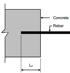
(ii) As is a common issue in developing countries, the construction was completed with very cheap materials. The high cost and unavailability of steel led to use of smooth reinforcement bars. After the collapse, officials cited underuse of proper steel rebar (to achieve redundancy) and bad cement in the reinforced concrete construction. Had there been more reinforcement, the collapse may have been localized rather than progressive. [c]

(iii) Though initially designed to be a 5 story building used for office spaces, the final occupation of the building was as an 8-story industrial garment factory. At the time of collapse, the building appeared to be undergoing even further expansion. [a] The heavy machinery and crowded conditions of the garment factories created extreme, uneven loading that surpassed the strength of the structure. There was blatant disregard for building codes by the owner.

(iv) Bangladesh has the lowest wages in the world for garment workers, with over 5,000 factories manufacturing for retailers worldwide paying its over 4 million workers an average of $38 USD per month. [b] Building codes are ignored and inspections are irregular—a consequence of bribery and the political clout of factory owners. Hundreds of others were also killed in factory fires or collapses that year. [d]

[f, g]

Location: Enschede, the Netherlands
Failure: Roof collapse during extension work at the De Grolsch Veste stadium of FC Twente
Date: July 7, 2011
Deaths: 2

Architecture Firm: IAA Architecten
Structural Engineering Firm: VolkerWessels

Stadium Roof Collapse  Stadium Roof Collapse (1)  Stadium Roof Collapse (2)  Stadium Roof Collapse (3)

[1, 2, 3, 4]

On July 7, 2011, during work to extend the De Grolsch Veste stadium, the roof of the extension collapsed. FC Twente wanted to increase stadium capacity by further extending the L-shaped extension completed in 2008 into a U-shaped one [a].

The investigation conducted by the Dutch Safety Board revealed that the roof structure’s insufficient stability, and therefore the risk of collapse, was caused by several factors. The main factor was the absence of essential coupling pipes at the back ends of the roof beams and stabilizing connections in the roof structure. During assembly of the roof beams, steel cables were used as a temporary stabilizing measure. The last stabilizing cable was removed on the day of the incident. In addition, the roof structure was already being subjected to additional loading by a video wall, suspension bridges, piles of roofing sheets and the workers present. The investigation also revealed that the roof structure was being subjected to additional loading as a result of dimensional differences between the concrete beams of the stand, the foundation of the steel structure and the steel structure itself. These dimensional deviations in combination with insufficient adjustment options mean that parts of the roof structure could only be inserted by exerting deforming forces. The deformation caused additional tension that reduced the load-bearing capacity. The combination of tensions in the structure as a result of its own weight, dimensional deviations, the load already present and the absence of stabilizing measures caused one of the roof beams to fail as a result of the forces to which it was subjected, which initiated a total collapse [a].

As a result of this accident, twelve workers fell from a great height. Two workers were killed and nine injured, a few of them critically. One worker escaped with bodily injury [a].

  
[
1,2]

Architect: Uehara Haruo

Fukushima Daiichi Nuclear Power Plant is a disabled nuclear power plant located on an 860 acre site in the town of Okuma and Futaba in the Futaba District of Fukushima Prefecture, Japan.  The power plant was first commissioned in 1971, and it consisted of six boiling water reactors which drove electrical generators.  This made Daiichi one of the 15 largest nuclear power stations in the world [B].

The Daiichi Power Plant suffered major damage from the 9.0 earthquake and tsunami that hit Japan on March 11, 2011.  The fifteen meter tsunami disabled the power supply and cooling of three Daiichi reactors.  All three cores largely melted in the first three days.   The accident was rated 7 on the INES scale, due to high radioactive released over days 4 to 6.  Apart from cooling, the main task was to prevent release of radioactive materials, particularly in contaminated water leaked from the three units.  There were no deaths or cases of radiation sickness, but over one hundred thousand people had to be evacuated from their homes to ensure their safety [A].

The catastrophic accident at the power plant was the result of loss of offsite power caused by the earthquake, coupled with the loss of onsite power and the ultimate heat sink caused by the tsunami.  The first image shows where the earthquake happened.  Without a source of electrical power, the systems and components used to keep the fuel in the reactors cooled were not able to function.  Even though people tried to cool the reactors, they were unsuccessful in preventing the fuel from overheating and melting.  In addition, hydrogen generated during the accidents collected within the reactor building and caused explosions in the upper potions of the Units’ reactor buildings, this is shown in the second image.  There was significant damage to the top floors and exposure of the spent fuel pools to the environment.  The Nuclear Energy Agency member countries decided to alter the work priorities of the NEA standing technical committees in order to assess the accident and to identify safety lessons.  The NEA had devoted significant efforts to directly supporting the technical needs of the Japanese government, with this assistance primarily focusing on the recovery of land and decontamination, the development and implementation of national reviews and stress tests, and enhancements to the regulatory infrastructure [C].

BM2  BM1  BM3  BM4
[
1, 2, 3, 4]

Failure: Minaret
Location: Meknes, Morocco
Year: 2010
Type: Collapse
Deaths: 41

Bab Berdieyinne Mosque suffered tragedy when the ceiling as well as part of the structural walls of its minaret collapsed into the courtyard on February 19, 2010 [a].

Officials blamed a series of heavy rains for weakening the structure just before the collapse [b], but further analysis revealed several characteristics that contributed to the minaret’s ultimate demise. The 400 year old mosque was composed of rammed earth, or man-made sedimentary rock, making it particularly sensitive to prolonged moisture exposure [c]. The foundation of the site lacked proper drainage, subjecting the structural walls to constant damp conditions—weakening their overall stability [d]. As seen in Figure 2 above, proof of further foundation instability could be seen by the slight tilt of the minaret [f]. In addition, the foundation had been described as insufficiently proportioned [e].

Officials had been criticized prior to the collapse for their negligence of the mosque; multiple cracks were visible in the exterior, one of which was estimated to be 10 meters long [e]. The Imam, or worship leader, of the mosque had requested the mosque be closed for a week for structural investigation but was denied [g].

Credit to Nour Bouhou for Arabic and French article translations.

051207-MPLS-006Metrodome-crop  Metrodome_Typical_Yarn_Tear_WPM Metrodome_Fabric_Panel_104_MSFC
[1,2,3]

The Metrodome was built in 1980 in Minneapolis, Minnesota and is home to the Minnesota Vikings, United FC, and the Golden Gophers.[a] The building will be demolished this year.[a] Hubert H. Humphrey Metrodome has been no stranger to failures involving its inflatable roof structure. “In fact, the December 12, 2010 roof collapse marks the fifth time in the Metrodome’s history the domed roof has failed. Three of the four previous roof collapses, in 1981, 1982, and 1983, have been attributed to snow, while the fourth failure, in 1986, was due to strong winds.” [b] A severe winter storm moved into the Minneapolis region on Saturday, December 11. The storm dumped more than seventeen inches of snow in the Minneapolis area. [b] Anticipating the approaching storm, maintenance crews at the Metrodome took preventative measures by heating the internal temperature of the dome to around 80 degrees while pumping warm air into the cavity separating the inner and outer layers of the roof structure.[c]

At approximately 5:03 A.M. on Sunday December 12, 2010, a sliding mass of snow and ice broke free and slid down the roof, slicing a gaping hole in fabric panel number 104, seen in Figure 3. Although the internal pressurization system of the Metrodome was designed to compensate for minor tears, a hole of this magnitude resulted in the depressurization of the space and ultimately the collapse of the dome. Upon impact with roof equipment, the sliding mass caused tears in fabric panel numbers 43 and 44, directly over midfield.[b]

“On December 12th, a series of firms were contacted to assess the damage that had been done to the Metrodome roof structure.According to the Metropolitan Sports Facilities Commission, it was unanimously accepted that the deflation of the dome was caused by sliding snow and ice impacting the ring beam along the perimeter of the roof structure, rupturing the roof fabric at panel number 104. The tear in this panel caused the loss of internal building pressure resulting in the deflation of the air supported fabric.”[b] Birdair Inc., reported numerous minor tears and abrasions in the fabric. Their examination revealed the loss of the Polytetrafluoroethylene (PTFE) protective coating on the fabric membrane and the formation of cavities at the intersection of glass yarns within the inner fabric. If these depressions reached the depth of the inner woven glass yarns they would have been exposed to the elements, and the infiltration of moisture would ultimately weaken them. The ring beam and columns, and cables were inspected and deemed useable for future use. [b]

Overview of facility  09BFRL024_cowboys_stadium_cropped_LR  North End  South End

[1, 2, 3, 4]

Structure: Dallas Cowboys Practice Facility
Location: Irving, Texas
Year of Construction: 2003
Year of Failure: 2009
Type of Failure: Structural
Structural Engineer: Enrique Tabak
Construction Firm: Summit Structures LLC

The Dallas Cowboys indoor practice facility collapsed on May 9, 2009 during a severe thunderstorm. The facility, designed and constructed in 2003, was a fabric-covered tubular steel frame structure. In 2008, it was upgraded with additional purlins, new roof covering, and reinforcements for a few members. About 70 people were in the practice facility upon collapse and 12 of them were injured.

To better understand the collapse, it was estimated that at the time of collapse the wind speed were 55 to 65 mph predominantly in the westerly direction. The wind speed was well below the specified 90 mph design wind speed by ASCE Standards for the time and location of collapse. But the wind loads used for the design were different from the calculated wind loads based on the provisions of ASCE Standards, “producing significantly lower design demands by a factor of up to 3.9” [a]. Another factor contributing to the collapse was that the frame member capacities in the design were larger than calculated capacities based on AISC specifications “by a factor of up to 3.0” [a].

The remaining two factors discovered were not miscalculations of construction standards, but just details that were not considered in the design. The joints at the knees of the frames produced large bending moments and shear forces in the chords of the frame. These were not considered in the design, “increasing demand-capacity ratios by a factor of up to 2.3” [a]. Also, the upgrades in 2008 only affected the “compressive capacity of selected members; the most critical members were not reinforced” [a].

The design assumed that the tension exterior fabric was going to provide lateral bracing for the frame. But what happens when the fabric is ripped by flying debris during a storm? The design also assumed that the building was “enclosed” for the sake of calculating internal wind pressure. But the door openings around the building and vents would classify the structure as “partially enclosed”. A rip in the fabric from debris could also result in a higher internal pressure. [a]

Likely Collapse Sequence: [a]

  • Buckling of inner chord in straight section of roof resulting in formation of a kink in the frame
  • Failures at the east and west knees allowed frame to sway eastward
  • Compressive failure of east keystone web led to tensile fracture of the inner and outer keystone chords at the ridge
  • Spread of individual frame failures in similar patterns, through load redistribution and loss of lateral bracing, resulted in total collapse of facility

Recommendations by NIST: [a]

  1. Concern for the use of fabric covering to provide lateral bracing for structural frames
  2. Determination of the appropriate enclosure classification in the calculation of internal pressures for design wind loads
  3. The ability of the structural system, including bracing, to maintain overall structural integrity

[1]

[1]

Failure: Truss Collapse

Year: 2007

Location: Minneapolis, MN

During rush hour traffic one early August evening, a bridge along Interstate 35 westbound across the Mississippi River, also known as Bridge 9340, experienced a structural failure resulting in a collapse into the river approximately 100 feet below [2]. A motion-activated camera nearby was able to capture a portion of the collapse, and can be viewed here. There were some casualties involved: according to the Minneapolis StarTribune, 13 people were killed and 145 were injured [3].

The bridge was originally built in the 1960’s and had undergone maintenance several times. At the time of the failure, the bridge was undergoing some renovations: four of its eight lanes were closed, diverting all traffic between the remaining four lanes. According to the official accident report, several pieces of heavy machinery/equipment and tons of concrete materials were on the bridge [4].There was additionally heavy traffic on the four lanes that were open.

After investigating the incident, several reasons for the failure were cited. First, the gusset plates used for the joints of the trusses were extremely thin and did not strengthen the bridge as much as it was intended to.

[5]

[5]

Additionally, two extra inches of concrete had been added to the road surface over the years, increasing the bridge’s total dead load by 20%. The failure could have been avoided had there been a more thorough inspection of the gussets and underlying structure, as well as had the bridge been appropriately reinforced when it became out of code over the years.

Big Dig Ceiling Collapse 1 Anchor Bolt DiagramBoston Big Dig Area

[1,2,3]

Structure: Central Artery/Tunnel Project
Location: Boston, MA
Years of Construction: 1991-2006
Year of Failure: 2006
Type of Failure: Ceiling Collapse
Planner: Boston Transportation Planning Review
Construction Firm: Bechtel Corporation and Parsons Brinckerhoff

The Big Dig project refers to the Central Artery/Tunnel Project and is recognized as the largest, most complex and technologically challenging highway project in the history of the United States. The tunnel replaced Boston’s deteriorating six-lane elevated Central Artery with an eight to ten lane underground highway. [a] The project began in 1991 but was plagued by escalating costs, scheduling overruns, leaks, design flaws, charges of poor execution and use of substandard materials, criminal arrests, and one death. $2.8 billion dollars was the original estimated cost, but the project finished out at $14.6 billion dollars, 9 years behind schedule and $8.6 billion dollars over budget (adjusted for inflation).

On July 10, 2006, approximately 26 tons of concrete ceiling panels and suspension hardware collapsed onto the roadway of the Interstate 90 Connector Tunnel, killing one and injuring another. The cause of this collapse was later determined to be due to inappropriate use of the epoxy anchors that held up the concrete ceiling panels. [2] Fast set epoxy was substituted for the standard epoxy, allowing for similar strength during testing, but displaying very poor creep resistance over long term loading. [b] Power Fasteners Inc, was later indicted on one count of involuntary manslaughter. [c]

Two other failures associated with the Big Dig are related to flooding [d] and soil [e].

Ice Rink Box Girder   Ice Rink Finger joints  Ice Rink Fail  Ice Rink

[1,2,3,4]

Structure: Bad Reichenhall Ice Rink
Location: Bad Reichenhall, Germany
Year of Failure: 2006
Year of Construction:1972
Type of Failure: Roof Collapse

The Bas Reichenhall Ice Rink [4] was in trouble as soon as the construction started. The combination of many failures along with lack of technical approval is what caused this building’s roof to collapse.

For this timber structure, they had used box girders that were over the maximum height of 1.20 meters at 2.87 meters. [1] [a] Also, because they used box girders, this gave an area for moisture and condensation to collect and it is not easy to get inside of the box girder to stop this problem so this problem was never visible. This was followed by the fact that there was no structural calculation check by an engineer to make sure the structure was following all guidelines. However, there were calculations to show that the original structure could support the snow load that made the roof collapse, but it was the deterioration of the structure over time that led to its downfall.

For the glue that held the box girders together at the finger joints [2], they used urea-formaldehyde which is not moisture resistant so it was not a wise choice to use that in a high humidity ice rink. [a]The glue was also not spread very well and so the quality of the connections on the girders was poor. Eventually the moisture in the ice rink along with leaks in the roof from bad maintenance caused this glue to deteriorate. This could have been prevented with resorcinol glue that is better for larger gluing gaps.

So basically the roof should not have fallen from a snow load, but it did because of poor construction quality, no maintenance and failure to seek approval on the structure. All of these weakened the structure over time and eventually allowed the roof to collapse under the snow load.[3]

picture 5  picture 6  picture 7  picture 8
[1, 2, 3, 4]

Architecture Firm: Aéroports de Paris or ADP (Paul Andreu)
Construction Firm:  Watson and Bredy, BESIX, HERVE and Léon Grosse,
Structural Engineering Firm: Sechaud et Bossuyt
[a]

Aéroport de Charles de Gaulle  is the largest airport in Paris, France and the second busiest airport in all of Europe after London Heathrow. It covers an area of about 8,000 acres, and has three major terminals. Terminal 2 was the largest of the three terminals, with 2E, the newest addition, designed to be the “the most powerful hub in Europe, ahead of Frankfurt and London”.  [b]

Leading the exciting 750M euro expansion to the terminal was the legendary French airport architect, Paul Andreu, who had designed the rest of CDG. It received rave reviews upon its inauguration for its “daring design and wide open spaces” and was called the “crown jewel of the CDG”. [c]

However, about eleven months after its inauguration on 23 May 2004, a substantial portion (about 30m) of the curved ceiling fell, killing four and injuring three travelers. The scene was described as “cataclysmic, like an earthquake”. [b]

Experts, at first, were unsure as to the cause of the collapse, considering that it had just been praised for its unique steel and glass design eleven months ago. Only later did it become clear that it was a combination of several factors that contributed to the disaster. [d]

One of the main factors that prompted the collapse was that the design for the building had very little margin for safety, so the construction process had to minutely exact in order for the building to be successful. [e]

The curved ceiling had three layers: an outer layer of glass, a middle layer consisting of a metal support structure, with the third layer being the concrete blocks that supported the metal and glass. It was found that the metal support structure was too deeply embedded in the concrete blocks, which caused cracking within the concrete, weakening the entire structure. It also placed a lot of tension on the outer layer in order to maintain stability. [b]

The architect, Paul Andreu, also blamed the construction company for not mixing and preparing the reinforced concrete properly, leading to its collapse. It was also found that rapid thermal expansion might have had an influence in causing the collapse, as in that particular day the temperature dropped substantially (from 25C to 4C). [e] [b]

The collapse of the “crown jewel” of the CDG was seen as a massive embarrassment to France in the international community as well as for the architect Paul Andreu. The terminal reopened again in 2008, after a 100M euro project to replace all the glass and steel with concrete in order to insure the same problems would not happen again. [c]


_39222640_chicago203apbody[1]       Deck4[2]

On June 29, 2003, there was a large party filled with Chicagoan young professionals taking place at an apartment building in Lincoln Park neighborhood on Chicago’s North Side.  The apartment building had first, second, and third story balconies.  There were large congregations of young adults out on the second and third floor balconies that night enjoying the festivities and a warm summer night in Chicago.[2]

About fifty people were on the third floor balcony when, shortly after midnight, the balcony collapsed.  The balcony came down taking the second and third floor balconies down into the basement with it.  After the wreckage was scoured and all people were recovered and accounted for it was determined 11 people had died (two more died of injuries) and 57 more people were injured.[2]

The collapse caused much controversy in Chicago, especially over the company LG Properties, the company which owned the property and had the balconies built.  Part of the blame went to overcrowding with many people saying the balconies should not have had more than thirty people on it at one time.[2]  However, poor construction was ultimately to blame.

For starters, the porch was built illegally without a permit.  There were also a multitude of building code violations:  The balconies jutted out a foot farther from the building than codes allowed, the area was 81 square feet larger than was permitted, the supports were inadequate, the floor was built with undersized lengths of wood, and the screws used to attach the balcony to the wall were too short.[2]

After an investigation, it was found that 21 other buildings owned by Philip Pappas, president of LG Properties, also had similar violations.  Pappas was fine $108,000 for the building code violations.  In addition, Pappas was sued by 27 affected families.  In the end, the balcony was built with steel and obeyed the building codes.[2]

This incident could have been avoided and thirteen young people would not have lost their lives that night had the owners and contractors gotten a permit and built within the parameters of the building codes.  Though the balcony collapsed due to overcrowding and overloading, it could have withstood that loading had it been soundly built.


structure  explosion  wtc  north tower
[1,2,3,4]

Failure: World Trade Center
Location: New York, New York
Year: 2001
Type: Terrorist Attack
Deaths: 2,763.
Architect: Minoru Yamasaki
Structural Engineer: John Skilling and Leslie E. Robertson
Construction Firm: Tishman Realty & Construction

The World Trade Center Towers in New York City were victims of a terrorist attack on September 11, 2001, which caused their collapse. The two, 110-story buildings, were actually designed to withstand the forces cause by a horizontal impact of a large commercial aircraft [a]. The structure was composed of a core of columns in the middle interior section as shown in figure 1. The perimeter of the building was composed of metal tubing that aided in the support of the floors, as horizontal floor trusses spanned from the tubing to the central core. The structure was also designed with redundancy, so that if a column were to fail, the building would still remain intact. Ronald Hamburger, a structural engineering studying the failure of the World Trade Center, said “because of its great structural redundancy, the load was distributed to other parts of the building [b].” He also stated that he has reason to believe that without fire, the building could have remained standing and be repaired [b].

The World Trade Center failed for multiple reasons. The fire and explosion (as seen in image 2) caused by the jet fuel of a Boeing 767 (as seen in image 4) was unaccounted for when designing the structure to support a collision of an airplane, and it ultimately led to the collapse of the World Trade Center. The prolonged heating of the steel columns caused the columns to experience creep, and for the yield strength of the columns to lower significantly [a]. The fire also caused the trusses that supported the floors to fall apart and because the fire had affected the columns and trusses on the top floor, the upper section of the building failed first. A domino effect occurred as the top floors fell straight down and crushed the floors beneath. The south tower failed after 56 minutes of being hit, and the north tower failed after 102 minutes [c]. An image of the aftermath of the world trade center collapse can be seen in image 3.

Niigata Apartment Buildings Overturn

Niigata Apartment Buildings Overturn

[1]

Location of Niigata
[
2]

Failure: Building Overturn
Year: 1964
Location: Niigata, Japan
Type: Earthquake – Liquefaction

On June 16. 1964, the city of Niigata experienced a magnitude 7.5 earthquake. Kawagishi-cho, a complex of eight 4-story apartment buildings with approximate dimensions of 30m by 8m, was built on reclaimed land. During the earthquake, the complex  experienced severe soil settlement, resulting in various degrees of tilting of up to 80° from the vertical (photo 1) [a]. Although the buildings had been designed and constructed to withstand the violent shaking, the soils beneath the foundations turned to “quicksand”. These reinforced concrete buildings sank into the earth and tilted [b].

The earthquake caused the peak surface acceleration of 0.16 g’s near the site. The buildings, which were built with shallow foundations, tilted because of the shear strength of the liquefied sand diminished during the earthquake. This process became known as liquefaction. Civil and geotechnical engineers around the world immediately became aware of the devastating potential of earthquake-induced ground failures that were rarely considered before in the design process. [d]

Liquefaction is a phenomenon in which the strength and stiffness of a soil is reduced by earthquake shaking or other rapid loading. Liquefaction occurs in saturated soils: that is, soils in which the space between individual particles is completely filled with water. The water exerts a pressure on the particles that influences how tightly they are pressed against each other. Prior to an earthquake, the water pressure is relatively low. However, earthquake shaking can cause the water pressure to increase to the point where the soil particles can readily slide by each other.   Earthquake shaking often triggers this increase in water pressure; however, construction-related activities, such as blasting, can also cause an increase in water pressure [e].

As more and more projects are being constructed in hazardous locations, the threat of liquefaction has grown. However, through careful evaluation and engineering, the risks of liquefaction can be mitigated. Since that Niigata earthquake, the methods of Earthquake Drains and Vibro-replacement  have been developed so as to mitigate the risk liquefaction [f]. 

The video below demonstrates the concept of liquefaction. Sand (loose sediment) was used and water added to create a saturated soil similar to that in nature.

[a] Milutin Srbulov, page 164, Practical Soil Dynamics: Case Studies in Earthquake and Geotechnical Engineering

Millennium Bridge
[
1]

Structure: Millennium Bridge
Location: London, England
Year of Failure: 2000
Type of Failure: Synchronous Lateral Excitation
Architect: Foster and Partners
Structural Engineer: ARUP
Construction Firm: Monberg & Thorsen and Sir Robert McAlpine

On June 10, 2000, the Millennium Bridge opened as the first pedestrian bridge in London in over 100 years. Designed by Foster and Partners and engineered by Arup, the Millennium Bridge was proclaimed as an engineering feat in its slender profile and expressed structure. On the day of it’s opening, nearly 100,000 people passed over the bridge, spanning across the River Thames from the Tate Modern to St. Paul’s cathedral. [a]

Almost immediately the bridge began to wobble from side to side. The oscillations increased to a magnitude of nearly 70 mm near the middle, large enough to force people to cling to the banisters. The engineers were immediately notified and attempted to mitigate the bridge sway by controlling the number of pedestrians. However, even smaller crowds, well under the bridge’s 2,000 person operational capacity induced lateral movement in the bridge. The Millennium Bridge was closed 2 days later in order to diagnose and remedy the failure. [b]

wobble
[
2]

Several factors played into the unforeseen behavior of the bridge under pedestrian load. Arup engineers understood that the normal gait of humans generates a small lateral force for balancing purposes. However, engineers expected the random step of the pedestrians to largely offset this lateral force, and focused more on the vertical force caused by walking that has been understood and documented in design code and specifications. [c]

What caused this underestimation to manifest itself in the Millennium Bridge more so than many other pedestrian bridges around the world had to do with the natural frequency of the bridge itself. Due to the sleek design of the bridge, the suspension cables run along side instead of well above the bridge as in the Golden Gate Bridge and other traditional suspension bridges. These suspension cables, therefore, were pulled more tightly between supports, increasing their tension and decreasing their length. These properties of the suspension cables along with the relatively light aluminum decking of the walkway, acted to raise the natural frequency of the bridge to very closely match the frequency of the human walk. [b]

The Arup engineers were correct in their assumption that people walk in a random fashion, but failed to understand that even in a random model, a portion of the people are destined to “match step.” In the case of the Millennium Bridge, the unintentional matching of step by a fraction of the crowd was able to induce lateral motion in the bridge. As the motion manifested itself, more and more people began to match step with the motion in order to balance themselves, therefore, magnifying the oscillation of the bridge. [a]

There were two options available to correct the failure. One option was to stiffen the bridge considerably to move the frequency outside of the excitation zone. The other option was to add a system of dampers to absorb and dissipate the lateral energy applied by the pedestrians. It was decided that stiffening the bridge would cause too serious a change to its physical appearance, and therefore, an extensive dampening system was designed. Arup underwent a $8.9 million dollar renovation installing 91 dampers in the bridge in order to disrupt the natural frequency and absorb the energy of the lateral movement. The Millennium Bridge reopened 18 months later. [c]

viscous damper3d_mods_06
[
3]                                  [4]

Knick Ei Collapse Close-Up "Knick-Ei" Collapse 1 Knick Ei Collase 2[1,2,3]

Building/Building Structure: Glass Dome Failure
Location: Halstenbek, Schleswig-Holstein, Germany
Year of Construction: 1995
Year(s) of Failure: 1997, 1998
Type(s) of Failure: Severe Weather, Improper Construction
Architect: Poitiers & Partner
Structural Engineer: Schlaich Bergermann & Partner
Construction Firm: Community Halstenbek

Construction of the Sporthalle Feldstraße, later known as the “Knick-Ei” (dented egg), began in September 1995. The underground sports hall saw its glass dome covering fall twice before its demolition in 2005.

The first collapse occurred in the early morning hours of February 5, 1997. There were no workers on the site during the collapse.  Dr. Wilfried Krätzig , a german civil engineer and professor of structural analysis, determined that the collapse was due to severe storms and improper construction. He did not find any errors in the structural analysis of the dome; thus it was decided to rebuild the dome. [a]

The dome collapsed a second time a 16 months later, just two months before its scheduled opening, on June 27, 1998. After this collapse, the city of Halstenbek filed a lawsuit against all companies involved in the construction to determine who was to blame for the collapse.” [b]

slideshow_559252_3 [1slideshow_559270_9 [2]

Scheduled to house the closing ceremonies of the 1996 Summer Olympics, the $207 million Atlanta Olympic Stadium, also known as the Centennial Olympic Stadium, was halted in construction due to the collapse of one of the 6 light towers that were being erected. This accident occurred after the celebration of the completion of the framework that utilized 8,000 tons of steel. Engineers state that this construction failure gave way to the metal buckling. [a]
After examining the causes to this failure, it was found that this event happened due to a design error of the tower light. The structural engineer was not aware of the progress of the construction of the tower light so he did not consider the error as an emergency. As a result, the structural engineer waited ten days before warning the architect about the design error. This miscommunication let to the error not being carried out in time, which ended up killing one iron worker and injuring another. [b] The six towers that are located above the upper levels were designed by “Heery International Inc., Rosser International Inc., and Becket Company of Minneapolis”. Due to this fatal and tragic accident, the structural engineer’s engineering registration was suspended for 3 years, who, in this case, was a man named Brian Miraki. [c]

Structural Engineer: Brian Miraki

Construction Companies: Heery International Inc., Rosser International Inc., and Becket Company of Minneapolis

1                                                 2

Location: Seoul, South Korea
Year: 1995
Type: Structural Overload, Punching Shear

The building began to crack in the ceiling two months prior to its complete destruction. The main causes for the building failure turned out to be its structural overload as well as punching shear in flat slabs. During the construction, the format of the building’s structural system was designed as a residential apartment with four floors. However, the owner of the building changed it to a large 5-level retail facility which required much more load resisting structures. He replaced the original construction team that was being skeptical about the feasibility of the design, and then cut away a number of columns. Moreover, the size of the columns was reduced in order to install escalators and a book store which was not planned in the original project plan. On the fifth floor slab, not only the restaurants with heavy equipment but also the hot water pipes in concrete base for heat radiation transferred extra loads to the columns, and resulted in a failure to support the floor [a].

Another factor that accelerated the collapse was the HVAC units on the roof. The system weighted total 87 tons including the air conditioning fans and cooling towers. After 22months of operation, the department store was receiving continuous complain regarding the noise that the fans were producing. Instead of lifting and mobilizing the system by using crane, the managers decided to drag them to the other side so that they could reduce the equipment cost. Such action pushed down the roof to sink, deteriorating the whole building even more with a phenomenon called punching shear. Punching shear occurs when the slab exceeds its own weight limit by forcing the column to punch through the roof [a].

The failure took place in June, 1995, suffering 501 casualties and approximately 1,400 injuries. Improper structural modifications and building management remarked such event as the deadliest disaster in South Korean construction history [a].

   
[1,2]

Location: Paparoa National Park, New Zealand
Date: April 28th, 1995
Deaths: 14
Type: Collapse

Construction: New Zealand Department of Conservation

Background: A class group of 17 students and a Department of Conservation guide were on the platform when it fell 98 ft onto the rocks below. The collapsed platform and rocks at the bottom of the chasm can be seen in the images above [a].

Cause: The platform had many causes for it’s ultimate failure. One of the major causes of the disaster was that the platform was not designed or constructed by a qualified engineer, but by the local DOC members. Parts of the structure were built off site and flown in, but the plans never made it to the site, so during construction no plans were followed [b]. The steps for the platform were supposed to act as a counterweight but they were not attached properly because the steel which should have tied the platform to the stairs was misplaced and a new order was never put in. A drill could not be found during the construction so instead of using bolts, nails were used to hold the members in place. There was no building consent ever obtained for the platform, and was also never registered for inspections. There was also a limit of 5 people maximum on the platform but no sign indicating this was ever erected.  [a]. The DOC blamed many of these causes due to being seriously under-funded and under-resourced [b]. The local triggers that lead to the disaster was that there was an excessive number of people on the platform, 17 to be exact, due to the lack of safety warning, and years later one of the survivors told the press that at the time of the failure the group was jumping up and down on the platform. Though, experts say that the platform was bound to fail regardless of the jumping.

After Effect: After the failure of the platform the DOC looked into their other 520 structure, of which 65 were closed for repairs. Signs were put up all over the park displaying the maximum number of people allowed on the various platforms and bridges. The platform that failed was never rebuilt and a fence and warning sign were put up in their place [a].

Murrah BuildingAPM Memorial

[10,11]

Building: Alfred P. Murrah Federal Building
Location: Oklahoma City, Oklahoma, USA
Year of Construction: 1977 (completed)
Year of Failure: 1995
Architect: Wendell Locke of Locke, Wright and Associates

Overview
Located in downtown Oklahoma City, Oklahoma, USA, the Alfred P. Murrah Federal Building was a nine-story, reinforced concrete frame structure that housed seventeen government agencies and 361 occupants (some of whom were children) [1]. Its construction was completed in 1976 [8]. To capitalize on available natural light, its north facade featured a full-height curtain wall system [1].

The building was the target of an April 1995 domestic terrorist attack for which Timothy McVeigh was convicted and executed in 2001 [2]. At 9:02 am on April 19, McVeigh detonated approximately 4800 pounds of explosive material contained in a truck outside the north facade of the federal building [3]. One hundred and sixty-eight people, including 19 children, were killed in the attack, and hundreds more were injured [4] . Additionally, about 300 buildings in the vicinity were damaged or destroyed [4].

Structural Failure Mechanisms
Most investigations into the failure mechanism of the building agree that the collapse resulted from four columns on the north side of the building being structurally compromised, whether directly from the bomb or from the failure of other structural components. The building’s structural system was found by the FEMA Building Performance Assessment Team (BPAT) to have been in compliance with all the codes and provisions at the time for the design and construction of a reinforced concrete frame structure [7].
The BPAT reported that since the curtain wall offered no resistance to the blast wave, the wave propagated through the building, resulting in differential pressures on the floor slabs [7]. The pressures were greater on the underside of the floor slabs than on their top surfaces, resulting in upward loading [7]. The floor slabs were reinforced only at the bottom and therefore could not resist the upward force [7]. The uplift caused reverse flexural and shear cracking of the floor slabs (see image below) [7].

After the blast wave, gravity loads caused the slabs to experience catenary action (see image below) [7]. As a result, the slabs failed in punching shear at one line of columns [7].

The catenary action also caused the third-floor transfer girder (which was cast in the slab) to rotate and be pulled inward, resulting in the progressive collapse of the building [7]. (A progressive or disproportionate collapse occurs when an event that should cause localized damage instead causes most or all of the structure to collapse, out of proportion to the initial damage [6].) The collapse of these floor slabs is thought to have caused the buckling of two columns (G16, G24) [7].

Some dispute the generally-accepted theory of the bombing, most notably in The Partin Report, which claims that the damage to the building could not have resulted from the truck bomb alone, but would have required separate demolition charges to destroy columns in the building [3].
The building suffered severe structural damage, as is evident in the picture below, and was demolished about a month after the bombing [5].

Murrah Building 2

Robert Hill, PE of the Dallas-based structural engineering firm Brockette, Davis and Drake determined that the main tower of the building was damaged beyond repair [5]. The mode of demolition chosen was implosion. Because implosion depends partly on the structural integrity of the structure being demolished to control its fall, reconstruction operations had to be carried out to strengthen the remains of the Murrah building before demolition could take place [5]. Less than 150 pounds of explosives were used in the implosion of the building, which took seven seconds [5].

Changes to Design of Reinforced Concrete Structures
In 1997, Hinman and Hammond suggested changes to the design of reinforced concrete structures, based on a case study of the effects of the Oklahoma City bombing on the Murrah building [6]. These suggestions focused on preventing progressive collapse. In the case of the Murrah building, Hinman and Hammond assert that only 4% of the building area was destroyed directly by the bomb blast, but 42% of the building was further destroyed due to progressive collapse [6]. They suggest that redundant load paths and “mechanical fuses” should be provided in the structural system, so that elements can fail without causing progressive collapse [6].

Gitanjali Bhattacharjee

Building: North Tower of the World Trade Center
Location: New York, NY
Years of completion: 1973
Year of failure: 1993
Type: Terrorist attack
Architect: Minoru Yamasaki
Structural Engineer: John Skilling and Leslie E. Robertson
Construction Firm: Tishman Realty & Construction

wtc  WORLD TRADE wtc3
[1, 2, 3]

Seven suspects organized and bombed the World Trade Center on February 26, 1993. The 1,200 lb. bomb was said to have been in a truck on the ground level parking garage of the North Tower [a][b]. The goal of the terrorists was to bomb the South Tower so that the failing debris would knock down the South Tower, luckily this was not a success [c].

The effects of the blast were quiet severe. On the ground level, where the bomb was detonated, a large crater approximately 130 feet by 150 feet was opened, causing reinforced concrete and debris to fall to the below level garages. 9 steel columns were damaged leaving them without lateral support. Several walls collapsed and nearby elevator shafts, stairways and enclosures were damaged. Mechanical, electrical, and plumbing systems were all ruined on the ground level and the four levels below [d]. A full diagram of damages can be seen in figure 1 above.

On the level above the explosion, approximately a 5,000 sf hole was opened, along with damage to many walls and elevators. On this level, seven steel columns were destroyed leaving almost no lateral support. On the second and third levels above the explosion, a large section of concrete was cracked and shifted. A wall of glass windows blown out between the tower and a nearby hotel, allowing large amounts of smoke to pass through [d].

The structural failures occurred because concrete fell placing heavier loads on levels below. Fire and the bursting of several pipes caused excessive heat to materials of the columns, beam, and walls. Luckily, the building was able to be repaired. Six people died during this terrorist attack, and over 1,000 were wounded. Higher safety regulations were put in place concerning terrorist precautions and evacuation protocol [e].

  [1]    [2]

On December 11, 1993 at 1:35pm, the first tower of the Highland Towers apartment complex in Selangor, Malaysia fell, ultimately killing 48 people. The cause of failure was attributed to a landslide that occurred due to pipes that burst, allowing for the barren ground near the site to wash away [a].

A pipe system was originally placed on a hill nearby the towers to divert water from a stream that normally flowed onto the site. Trees had also been previously cleared from that hill for a separate housing development project, so the soil had no protection against erosion. During a 10-day monsoon, the pipes burst from the large amount of water flowing through them, letting that volume of water flow down the hill. The combination of monsoon rains and loose soil led to a landslide that brought Block One of the Highland Towers with it. A mass of mud equivalent to 200 jumbo-jets (around 100,000 sq. meters)  came sliding down the hill, breaking retaining walls, and finally destroying the pier foundation system of the tower [b] (please see Figure 3). The tower was able to stand for a few days, and showed warning signs of failure such as cracked walls and pavements. However, Tower One was destined to fall. Luckily, some residents were able to evacuate the building prior to the collapse because they knew something was wrong. Residents in the neighboring Towers Two & Three were quickly evacuated, and not allowed to return for fear of those towers also collapsing [c].

   [3]

Tragedies like this can be difficult to prevent. However, certain measures can be taken to protect buildings from landslides. Firstly, the effects of erosion should be taken into account when clearing a plot of land. Secondly, the retaining walls should be designed to be stronger as well as go deeper in the ground to further prevent large masses of land shifting [d] (please see Figure 4). In Malaysia, where there are times of the year with constant downpour, it is difficult to design for such catastrophes. In this case, it seemed that all the necessary precautions had been taken to prevent such a tragedy.

  [4]

Since this was such a tragedy, the names of the architects, engineers, and constructors were left anonymous during litigation.

Failure: Precast Beam Collapse
Location: Pittsburgh, Pennsylvania
Year: 1990
Type: Development length of rebar was too short
Deaths: 1


terminal

[1] Midfield Terminal as it stands today

On August 14, 1990, workers at the Pittsburgh Midfield Terminal were placing a concrete floor plank on top of a precast concrete beam causing the collapse of the beam. The collapse resulted in the death of one man and the injury of another and shut down the work site for only a couple of days [a].

Investigations immediately followed the mishap as many wondered who was to blame: designers or constructors? When interviewed, the design engineer of the beam, Hanna Ghobrial, said that “the beam was not made according to specifications and had reinforcing rods in the wrong places” [b]. Upon further investigation, Deputy Gilkes of Pittsburgh said that “the accident resulted from the failure of fabricators and inspectors to read the shop drawings in the same way the design engineer and consultant did” [c]. Ultimately, the root of this failure was in the construction of the beam and not in the design.

To understand what went wrong in the design, one must first understand how a reinforced concrete beam is designed. Rebar reinforcement runs throughout much of the tension side of the concrete beam because concrete is weak in tension while steel is very strong in tension. In order for the reinforcement steel to ‘work’ (carry the load it was designed for) it must yield and in order to yield, the concrete must place a certain amount of tension force on the steel reinforcement. The farther a beam is embedded into a concrete beam, the more force the concrete beam places on it–this length of embedment is called the development length as seen in Figure [3]. The development length of rebar reinforcement in a concrete beam is “the shortest distance over which a bar can achieve its full capacity” [d].This is where the Pittsburgh construction workers made a mistake. It was discovered that the reinforcement was embedded a mere 7.5″ into the beam–a much shorter distance than what the development equation in Figure [2] calls for in a beam of this size:


Screen Shot 2014-02-06 at 8.30.21 AM

[2] Development length equation for bars in tension depends on a number of factors including the bar size, spacing, and more

rebar

[3] Development length, ld, of a reinforcement steel bar into a concrete beam

Due to the short development length, the precast concrete beam ‘pulled out’ of the wall, collapsing and kill one worker. For a better understand of what development length is please refer to Figure [4]. In this image, the rectangle directly above the Elevation View label is the column and the two rectangles running perpendicular to it are top and side views of the beam. While the image shows a beam as a continuous member on either side of the column, in fact, the columns are the members that extend continuously while the beam must split on either side of the column and anchored safely to the column so that it will essentially function as one whole beam. In reinforced concrete it is common for some reinforcement bars to be shorter than others as the moment capacity (the load the bars need to carry) varies along the beam. Two of the reinforcement bars (the red bars) have a shortened development length (the distance from the dotted line, the face of the column, to the end of the bar) because that is where the moment capacity drops and they are no longer needed throughout the rest of the beam [e]. This is similar to what happened in the Pittsburgh collapse, however, in this figure there are three other reinforcement bars that continue to carry the load throughout the beam while in the Pittsburgh terminal there was not. The lack of reinforcement in the beam caused the beam to pull away from the column causing the ultimate collapse and fatality.


Screen Shot 2014-02-06 at 8.36.27 AM

[4] Comprehensive picture of development length, ld

  • [e] Wight, James. Reinforced Concrete Mechanics and Design. 6th Ed. 373-380. Print.

Pavia 2 Pavia 1    Pavia 3
[1,2,3]

The Civic Tower of Pavia was built in Pavia, Italy in the 11th century. It was located adjacent to the Pavia Cathedral shown in Figure 2. At its peak Pavia was home to many similar towers, when it became known as the “City of 100 Towers”. In 1583 construction began on the addition of a belfry to the top of the tower. [a] The Civic Tower of Pavia was built in three to four different stages, starting in 1060 and finally completed in 1598 with the completion of the belfry tower.
On the morning of March 18, 1989, bricks began falling from the tower, leading to its sudden collapse. The entire tower was reduced to a pile of rubble shown in Figure 1. The collapse killed 4 people and injured 15 more. The reason for the collapse was speculated and many tests were done to determine the reason for failure.
The tower was constructed as many tall towers of the time, with thick walls at the base, getting thinner as it nears the top. The walls were made of layers, with external layers of roman brick masonry between 150 to 490 mm thick. Between the outer layers was a particular ancient concrete consisting of lime mortar, river gravel and recycled bricks. At one point in the tower’s lifetime, a permanent staircase was built within the wall thickness. [b]
The reason for failure is still currently unknown. Many steps were taken to determine the reason for failure. A search began for the original documents of the towers construction. The reconstruction of the geometry of the tower then began to ensure the tower was designed sufficiently. Geognostic tests were ran to define the consistency and mechanical properties of the soil beneath and around the tower. An analysis was also done on the chemical, physical and mineralogical make-up of the mortars, bricks and stones forming the masonry to see if there was an overall decay that led to the structural failure. Compressive stress tests were conducted on masonry blocks from the ruins to determine if the load exceeded the capabilities of the materials, and many stress analyses of the tower assuming elastic behavior. [b]
A definite conclusion was never reached regarding the single reason for the towers failure. However, many speculations were made. For many, the 16th century belfry addition may have prompted the collapse. [c] The added weight plus the excavation of the wall to insert a staircase may have severely weakened the structure. Masonry creep could also have contributed to the weakness of the structure. Creep depends on the stress level and the temperature and humidity conditions and are increased by cyclic action due to wind, temperature variations or vibrations induced by traffic or the ringing of the bell. [d] The collapse of the Civic Tower of Pavia led to the serious investigation of stabilizing the Tower of Pisa.
Ultimately, many speculate that old age accelerated by a slow chemical reaction between the medieval and more modern mortars used in the stonework could have led to the towers collapse.[a] The definite reason for collapse though has never been determined, and the spot where the tower once stood houses a shrine of the remains of what once was, as seen in Figure 3 above.

aon center  Amoco Hysteresis
[1,2]

Location: Chicago, Illinois
Year: 1989
Type: Façade Failure due to Thermal Hysteresis

The failure of the Amoco Building in Chicago serves as arguably the most infamous example of thermal hysteresis. Constructed as the headquarters for Standard Oil of Indiana in 1974, the building changed names along with the company in 1985 to become the Amoco Building. It was then later sold and renamed in 1999 and is now called the Aon Center, seen in Figure 1 above.[a] At the time it was completed, the tower’s height of 1,136 feet made it the tallest building in Chicago and the fourth tallest building in the world.[b]

For the façade, the architect Edward Durell Stone recommended to his client that they use thin marble slabs, stating that they would be “longlasting and outstanding.”[b] The claim had some merit; Italian Carrara marble had been used by Michelangelo to sculpt his masterpiece David in the early 1500s and was selected by Alvar Aalto in his construction of the Finlandia Concert Hall in Helsinki – a building which eventually suffered the same fate as the Amoco Building.[c] Stone convinced Standard Oil that a Carrara marble skin would convey a sense of prestige befitting fifth largest energy company in the world.[b]  Following his recommendation, Standard oil imported almost 6,000 tons of the stone, which were then cut into 45 inch by 50 inch slabs 1 1/4 inches thick. Requiring 43,000 of these panels, the marble façade helped propel the project’s total cost up to $120 million.[b]

However, the panels lasted less than 15 years.[b] After years of exposure to Chicago’s large temperature swings, much of the façade began to deteriorate to dangerous levels. Known as thermal hysteresis, years of extreme thermal cycling caused the thin marble slabs to permanently bow outward, as seen in Figure 2 above. While marble is a brittle material, it exhibits some plastic behavior over long periods of exposure, resulting in permanent deformation and a substantial loss in flexural strength.[d]

Eventually every one of the 43,000 marble panels had to be taken down and replaced with granite from North Carolina, a repair which took 3 years to complete and cost $80 million.[e] “To recoup its costs, Amoco sued all parties involved: Edward Durell Stone & Associates as well as Perkins & Will, the tower’s architects; Turner Construction of New York, the general contractor; Peter Bratti Associates Inc., a New York firm that installed the marble; and Alberto Bufalini Successori, the Italian marble supplier.”[b] The parties ended up settling out of court, with the results kept confidential.[f] Still, the building serves as a cautionary tale for those who might attempt to use marble for their building facades.

[c] Siegesmund, S; Ruedrich, J; Koch, A. “Marble Bowing: Comparative Studies of Three Different Public Building Facades.” Environmental Geology 56, no. 3 (December 2008): 473-494.

[d] Newlin, J; Jimenez, G. A; Hester, D; McIntosh Blank, L. “Thin Marble Facades: History, Evaluation, and Maintenance.” Structures Congress, 2010 ASCE: 1051-1062.

[f] Hook, G. “Look Out Below! The Amoco Building Cladding Failure.” Progressive Architecture, 75, no. 2 (1994): 58-61.

(1989: East Coldenham Elementary School)

1
[1]

2
[2]

Building: East Coldenham Elementary
Location: Newburgh, NY
Year of construction: 1959
Year of failure: 1989
Type of failure: Exterior wall collapse

November 16th 1989 12:30 pm.

During a large storm, tornado force winds blew against a wall section of the cafeteria during lunchtime at East Coldenham Elementary School in Newburgh, NY. The high pressure caused by the winds against the wall section caused the wall to collapse in on the cafeteria.

“Shards of glass flew across the cafeteria; seconds later, the entire wall collapsed.” said Principal Harvey Gregory, who had been in the cafeteria at the time of the accident. [a]

Dining tables and chairs hurtled through the air as an entire wall of concrete blocks and glass crashed down, striking and burying the children. Out of the more than 120 students that were in the cafeteria at the time, most between 7 and 8 years old, 9 children were killed and dozens of others were injured.[b]

The wall was a cavity-type wall composed of a 4-inch exterior veneer of bricks, a 2-inch air cavity and 8-inch concrete blocks on the inside. The concrete blocks had no interior reinforcement. The wall was approximately 40 feet wide, 25 feet tall and was surrounded on all sides by windows set in aluminum mullions. With this setup the wall had a fixed support at the bottom and virtually no lateral support on the top. As the wind blew down on the wall, the moment at the cantilevered support at the bottom of the wall exceeded the cracking stress in the concrete and the entire wall cracked along the bottom edge and fell in on the cafeteria. [c]

If the wall had lateral support at the top and/or interior steel reinforcement then the collapse would not have happened. The cantilevered wall with no interior reinforcement could not withstand the tornado force winds and was bound to collapse.

Architect: John Graham and Company
Rochester, New York
Constructed: 1973

Lincoln First Bank Tower  Thermal Hysteresis: Stone Panel Bowing, Causes and Solutions
[12]

Originally constructed as the Rochester Lincoln First Bank in 1973 by architect Jack Follete of John Graham and Company, the tallest building in Rochester, New York’s marble façade crumbled to the sidewalk by the mid 1980’s. [a]

The skyscraper is located in an area called “Clinton Square” and is a prime example of “late modern commercial architecture” as shown in image 1. The exterior has 24 load bearing steel tubes and 24 hollow columns that transport utilities throughout the building. The original design included marble plating on all the outer columns. [b] The marble covering was thinner than standard “values in architecture reference books” and absorbed more water and pollutants than expected. Marble plates visibly deformed and became a public concern. The added weight of pollutants and water caused the marble façade to “crumble” under its own weight. As the marble slabs fell off the 398 foot structure, the sidewalks had to be closed and painted plywood was fixed to the building while solutions were discussed. Engineers brought in to “judge” the façade condemned it. [c] Interior marble was not a safety hazard and could remain up while the exterior marble was replaced with painted aluminum. [a]

The exterior replacement of 203,000 square feet of marble cost the tower’s owner almost $20 million and the repairs stretched over three years. The marble being torn down had deformed to the point of being unusable for any other purposes and was discarded. The marble sheeting was a new material at the time the Lincoln First Bank Tower was designed. Unfortunately, the effects of the marble under heating and cooling were not known and a few other buildings were clad in the marble sheeting. It was determined after the failure of Lincoln First Bank Tower that the crystalline structure of the thin marble sheets causes unequal, permanent deformation, as shown in image 2. [c]

Since the façade deformation and adhesion failure in the 1980’s, the Chase Tower has undergone a $30 million renovation and caused other office spaces in the Rochester area to become vacant. [d]

939_1hyatt_Edithyatt_6

Failure: Hyatt Regency Walkway Collapse
Location: Kansas City, MO
Year: 1981
Type: Connection failure
Deaths: 114

The Hyatt Regency walkway collapse was the deadliest structural collapse in the United States prior to the collapse of the World Trade Center in 2001. The failure occurred during a dance competition with approximately 1600 attendants, present both on the ground floor and the 2nd, 3rd, and 4th walkways. In the original, design three pairs of steel tie rods suspended from the ceiling supported the concrete walkways from box girders built up with two channel sections at the 2nd floor and 4th floor. The manufacturer supplying connections found that the proposed design called for complicated fabrication that may have created damage to the threads at the 4th floor. Instead he created an alternative design that included 6 pairs of steel rods, 3 connecting the 4th floor to the ceiling, the other 3 connecting the 2nd floor to the 4th floor walkway. This would require the 4th floor girder to support not only the weight of its own walkway, but also the weight of the 2nd floor walkway, which it was not designed for. The structural engineer failed to identify the problem after the drawings were returned and submitted for construction. The capacity sufficed for the dead load in the walkways, but the large live load of viewers on July 17th caused failure.The failure occurred in the welded joint connecting the channels. [1]

Connection Detail
Haag Engineering Investigation
NBC News Report 30 Years Later

1  2

[1, 2]

Date: November 21, 1980

Due to improper installation, galvanic action, and ground fault, a fire was started in The Deli, a restaurant on the main floor of the MGM Grand. This room was unoccupied but due to the open plenum throughout the main casino floor, the fire and smoke were able to spread rapidly throughout the main floor and into some of the upper floors of the hotel [b]. The end result was that 85 people died, mostly from smoke and fume inhalation, and millions of dollars in damages, reconstruction, and settlements [c]. The first of the three problems was caused by a ground fault. During installation, it was assumed that all grounding was to be carried by the aluminum conduit. The conduit was not correctly connected to a receptacle box which would lead to arcing currents if there was a break anywhere along the circuit [b]. The second problem was caused by the galvanic action that occurred when the aluminum conduit came into contact with copper pipe. Galvanic action occurs when two metals come into contact for an extended period of time and they begin to corrode. Over time, one metal will corrode faster, in this case, aluminum, which caused a break in the aluminum conduit and, in turn, the grounding path [b]. The final problem was improper installation. While pulling conducting wires through a conduit, the insulation around each conductor could be degraded due to the abrasive nature of the flexible conduit that was used in some sections. Temperature changes that occur over the cycling of the current can lead to the degradation of the insulation, as well, which would allow current to transfer from the conductor to the conduit [b]. These three problems by themselves are not usually a major problem or fire hazard, but the combination of the three allowed for the ignition of the construction materials and the propagation of the fire through the building.

Other Sources: http://en.wikipedia.org/wiki/MGM_Grand_fire

OLYMPUS DIGITAL CAMERA  Willow Island Tower Collapse 1
[1,2]

In 1978, the Allegheny Power System built a larger power plant at Willow Island, West Virginia.  In addition to two smaller units already on site, they were installing two generators with a total capacity of 1300 megawatts.  One cooling tower had already been built by April while a second was still in the process of being constructed.  On Thursday April 27, 1978 the second tower’s scaffolding collapsed while under construction killing 51 construction workers [a].

Willow Island Cooling Tower Collapse
[3]

The process of constructing the shell of the cooling tower is depicted in image [3].  As shown in the image, the scaffolding is supported between layers of concrete that have previously been poured.  A lift system is also added to the scaffolding form to allow the workers to haul up buckets of concrete to pour into place  new layers for the shell.  Each layer is called a lift.  On the day of the failure, the construction team was working on lift 29, 166 feet high, relying on the concrete from lift 28 to support them.  However, the concrete for lift 28 had been poured only 18 hours before the new scaffolding system was placed upon it.  Running tests after the collapse showed that the concrete from lift 28 had not yet dried to a compressive strength great enough to support the scaffolding system.  When the weight of the scaffolding system with the workers and the buckets of concrete was applied to the lift it failed causing it to collapse and bring down the scaffolding with it [a,b].  51 construction workers were on the scaffolding at the time of collapse, and all of them fell to their deaths [a].  However, the construction workers in the center of the tower were able to take cover under a concrete truck ramp and avoided fatalities [c].

Another cause of collapse was the anchor point used for lifting the buckets of concrete.  Initially the anchor point was located near the wall of the cooling tower, but had been moved close to the center of the tower changing how the lift system was transferring the load to the shell.  If the anchor point had not been moved and stayed near the shell wall, the effects of the construction loads would have been reduced to a point where lift 28 would not have failed [b].

This failure was easily avoidable had the construction team decided to ensure the concrete poured the day before had dried enough to support the loads being applied to it.  Additionally, had proper analysis been done before moving the anchor point of the lift, the issue of changing how the load was transferred to the shell could have been avoided entirely.

waterville snow2  [1]
Building: Waterville Junior High School
Location: Waterville, ME
Year of Construction: 1978
Year of Failure: 1978
Type of Failure: Roof collapse

On the first day the Waterville Junior High was opened, February 9, 1978, the roof collapsed in a classroom soon after a teacher noticed the ceiling was deflected.   Waterville, Maine had been experiencing one of the most severe snowstorms it had ever seen for two days prior to the collapse.  [a]

The collapse was determined to occur due to a singular cause which was failure of a joist in an open web joist system.  The architect accounted for a uniform snow load, however he did not account for snowdrift load which was the cause of the failure of the joist.  The school was divided into six sections, each a different elevation.  The collapse was in a section with a relatively low roof elevation.  Thus, during the snowstorm, snow was blown off of higher roof sections and drifted onto the roof section of the collapse, which also happened to be downwind. [a]

Computer analysis of the joists involved in the collapse revealed that the joist with the greatest load during the time of the collapse was Joist 3, as shown in the diagram below.  However, the dead load was calculated assuming a more realistic load distribution amongst Joists 2, 3, and 4.  Ultimately, the total snow load on these three joists was calculated to be 422 lb/ft while the allowable load was calculated to be 190 lb/ft.  The specific open web joists used in the roof were determined to be able to hold a load of up to 2.2 times the allowable load; however, this buffer was not wide enough to contain the difference between the actual and allowable loads.  The official and “most probable” cause of failure was said to be that the ultimate strength of either Joist 2, 3, or 4 was overcome by the snow load, and one of these joist failed.  This caused the forfeited load to rest on adjacent joists that were unfit to carry the added load, and several said joists failed. [a]

diagram[2]
In conclusion, snow drifting largely contributed to the snow load on the portion of the roof that collapsed.  The structural designer failed to consider snow drift loads because their nature was not recognized by the industry at the time.  Had he done so, the roof would probably not have collapsed, although it would be overloaded. [b]

by Nathan Simmons


[1, 2, 3, 4]

Failure: Hartford Civic Center roof collapse

Location: Hartford, Connecticut

Date: January 18, 1978 [A]

Cause: Connection

Fatalities: None

Mere hours after housing a sold-out University of Connecticut men’s basketball game [A], the Hartford Civic Center collapsed after days of heavy snowfall. While no one was inside the building at the time of the collapse, had the failure occurred hours earlier during the packed game this roof collapse would have surpassed the amount of casualties of the 9/11 attack [B]. Originally, reports blamed the extreme accumulation of snow on the roof for the collapse, since the roofs design was more flat and therefore allowed ice and snow to pile up. However, after more thorough investigations were conducted, engineers and other investigators reported that there far more serious causes that lead to this near tragedy.

A lack of communication during construction created a bad mix carelessness and improper implementation that would set up this failure. Instead of using the predefined bolt holes, the subcontractors on site decided to weld the panels of the roof to the support beams [C]. While this was enough to hold it together for five years, this on-site modification greatly affected the building’s ability to withstand the elements because the engineer’s original design of the space trusses, done by a complicated computer system, was designed solely for use of the bolt holes [C]. Because of this, the design for loads could not be met, leading to buckling of the top bars and ultimately collapse [C]. So it was not solely Mother Nature that felled the original Hartford Civic Center but rather human error.

Citicorp_Center-diagram  1-citicorp-center-ny  15

[1, 2, 3]

Completed in 1977, the Citigroup Center is a major skyscraper on the Manhattan skyline [a]. Even before construction began, the building faced challenges. A church owned the land in the corner where the tower was intended to go. As such, the entire building was lifted over the church and each of the four corners of the building was cantilevered. With this design, the church was able to sit beneath one corner of the tower yet head the structural engineer William LeMessurier placed the four columns supporting the structure in the center of each façade instead of on the sides [b].

In order to accommodate this placement of the columns, the forces of the building had to be redirected. In a common skyscraper, the forces are directed out and travel down the corners of the building. In the citigroup center, once forces travel to the perimeter, they are directed down an eccentric structure using lateral bracing to the center of each façade and down into the columns. This can be seen in Figure 1. Each of these lateral bracings are eight stories tall and as such there are a number of critical connections where each floor meets the lateral bracing [c]. This is where the building’s failure lies.

The original structural design by LeMessurier called for these connections to be welded and as such fixed. Yet in the transition from design plans to construction plans, a subcontractor suggested a change in these connections from welds to bolts, effectively changing the connections from fixed to pinned [c]. This was approved without much examination and the building was built.

It was only after construction was complete that LeMessurier took a further look into the nature of the structure. After analyzing the final structure, he realized that if a constant high speed wind held for five minutes hit the building from the right direction, the building would completely topple over. A wind of this magnitude was estimated to occur approximately every sixteen years. This failure would have wiped out a significant portion of Manhattan causing a domino effect of buildings and inevitably causing the deaths of thousands of people [c].

To correct the issue, construction crews worked under the cover of night to weld in reinforcement plates at each of the susceptible connections. Media was kept in the dark to the issue yet the Red Cross and local authorities were preparing for the worst case scenario. This scenario almost came to fruition as Hurricane Ella approached New York in the summer of 1978. At the last minute though, the hurricane switched paths and headed out to sea [d]. Luckily, the reinforced connections were completed before disaster could occur within about two months and with great cost to Citigroup. This obviously led to a string of litigation crossfire, yet the building was able to be stabilized and disaster was averted [e].

[a] http://wirednewyork.com/skyscrapers/citigroup/
[b] http://skyscraperpage.com/cities/?buildingID=1613
[c] How New York Escaped Tragedy http://www.youtube.com/watch?v=TZhgTewKhTQ
[d] http://www.cracked.com/article_19682_5-most-embarrassing-architectural-failures_p2.html
[e] PBS: Building Big http://www.pbslearningmedia.org/resource/phy03.sci.phys.mfw.bbskyscraper/citigroup-skyscraper-design-problem/


Hancock Tower, Boston   john-hancock-tower-boston-ma072   plywood
[1,2,3]

John Hancock Tower, Boston Mass.

Built: 1976
Architect: Henry Cobb of I.M. Pei and Partners
Engineer: Bruno Thurlimann (Swiss)
Date of Failure: 1973 while the building was still under construction (first account)
Failure: Falling Window Glass Panels, Swaying

The John Hancock Tower had many failures over a period of time, however it’s most well-known failure is that of the falling windows. When winds would reach anywhere near 45 mph the streets all around the high-rise would be closed off. Starting during its construction some of the 10,344 large panels of glass that comprised the façade of this reflective skyscraper began to fall off causing quite a bit of damage and concern. At one point over an acre of the building was covered in plywood which replaced the failed glass. The issue was found in the construction of the windows themselves. They were specially made of three layers: one layer of chromium, and an air gap, which gave the building its reflective quality, and two layers of glass on either side, all encased in a metal frame. This metal frame was bonded to the chromium; and this bond is what caused the failure[a]. It was too strong and didn’t allow the windows to expand or vibrate which windows naturally do, thus the panels were cracking at their connections to the building and plummeting to the sidewalk below. Eventually all the panels were replaced with single pain tempered glass – paid for at the expense of the original window manufacturer.

Other failures were a concern for an unstable foundation and an abnormal about of movement that cause occupants on higher levels to experience motion sickness. William LeMessurier, a famous Cambridge engineer addressed the buildings tendency to sway by installing something called a Tuned Mass Damper which acted like a gyroscope to help counteract the buildings motion. Later Thurlimann, when asked to review the structural stability of the tower, added lateral bracing to ensure the building would remain standing [b]. Today it is one of the safest skyscrapers and a much admired work of art.


Building:  Ronan Point
Location:  Newham, UK
Year of Construction:  1968
Year of Failure:  1968
Type of Failure:  Progressive Collapse
Construction Team:  Taylor Woodrow Anglian

Ronan_Point_-_Daily_Telegraph [1]

The Ronan Point disaster of Newham, UK occurred May of 1968 due to a gas explosion on the 18th floor.  When a tenant lit a match over their stove, an explosion destroyed her flat, consequently taking out the walls of the entire corner of that 22 storey building[2].   The explosion was the catalyst to the weaknesses in the design and construction at Ronan Point.  First of all, the Larsen-Neilson precast concrete system used for the structure was inappropriately applied.  The system was primarily for buildings six storeys tall, and the Ronan Point was 22 storyes[3].  This meant that extra live and dead loads of the building would not be appropriately handled if this Larsen-Neilson system were to be used.  Because of the minimal amount of joints connecting the prefabricated concrete pieces, the large loads of a large building would over stress the joints.  Configuring any building this way, much less a tall building, will not allow multiple paths for the building load forces to flow in case of a failed member.  The design team needed to acknowledge the safety hazards that come with larger residencies, but the cursory construction did not help the situation.  After analyzing the joints after the explosion, some of the joints were not screwed tightly.  Even more, voids filled with garbage were found in place of the appropriate construction material designated in construction documents[4].   It was a combination of several factors that made Ronan Point waiting for disaster.

800px-Ronan_36 [4]

 Ronan Point was repaired with blast plates after the initial building failure.  It was eventually torn down, floor-by-floor, to observe the joint connections of the precast large structural panels.  Consequently, the Modernist movement in England declined in popularity. Since the incident, the building industry learned many lessons:  one of progressive failure and another of “robustness” in design.  Because of the damage to one flat, the floors above and below it failed.  Failing this way placed many people in danger.  Out of Ronan Pont’s ashes came “robust” design, which plans for several paths for forces to travel[3].  As a result, if one joint fails, the rest of the building will stand.

tumblr_ljp4goYpCM1qd72qf [5]

empire2  empirestatebuilding  EmpireState  B25  [1, 2, 3, 4]

Failure: Empire State Building B-25 Plane Crash
Location: New York City, New York
Year: 1945
Type: Plane Crash
Deaths: 14

On a foggy day in July 1945 a B-25 Mitchell airplane crashed into the north side of the Empire State Building when flying low [a]. At the time, the Empire State building was the tallest building in the world since it’s completion in 1931, and remained in that title until 1970 when surpassed by the One World Trade Center.

The plane’s pilot was Lieutenant Colonel W.F. Smith, Jr. who planned to fly from Bedford, Massachusetts to Newark, New Jersey, with a co-pilot and another passenger. He was traveling approximately 250 MPH when he was warned by the La Guardia Airport control tower to land the plane. The tops of the New York skyscrapers, particularly the Empire State Building, would not be visible because of the fog. The Lieutenant ignored this warning and continued ahead. He was navigating through the skyscrapers, lost sight of where he was, and crashed directly in between the 78th and 80th floors of the Empire State Building. See Figure 2 above for an image of where the crash occurred and Figure 3 for an image of the exact plane collision area [b].

During the crash 14 people died, including the pilots and passenger on the plane. The 11 victims inside of the Empire State Building worked for the War Relief Services department of the National Catholic Welfare conference [a]. Some of these people burned from jet fuel ignition and the others were thrown out of the building. 25 other people were also seriously injured [c]. See Figure 1 for an image of the Empire State Building after the plane crash occurred. “The force of the impact sheared off the wings of the plane and propelled one of the two motors across the width of the building…[and] demolished the studio of Henry Hering” and “the other motor…crashed into an elevator shaft and fell…onto the top of an unoccupied elevator” [b]. The women in the elevator escaped with help from emergency crews after the auto-braking system had stopped the shaft from falling. Luckily, because of the weight of the building vs. the weight of the plane and its impact, the building barely swayed and was still structurally sound – despite the fires that ignited [b]. This building failure was caused by a lack of good judgment and foggy weather.

After this incident, the Federal Tort Claims Act was passed approximately a year later [d]. This Act let people sue the United States government in federal court for accidents of this nature. This was a long time coming, but after this incident some families sued the federal government, while some took a large sum of money for their loss.

There is still a missing stone in the façade of the Empire State Building where the plane crash occurred.

[b] Levy, Matthys, and Mario Salvadori. Why Buildings Fall Down: How Structures Fail. New York: W.W. Norton, 1992. Print.

[c] Wilson, Alex. “1945 Airplane Crash into the Empire State Building.” Disasters, Accidents, and Crises in American HistoryA Reference Guide to the Nation’s Most Catastrophic Events. Ballard C. Campbell. New York: Facts on File, 2008. 290-291. Facts on File Library of American History. Gale Virtual Reference Library. Web. 4 Feb. 2014.

 [1]  Screen Shot 2014-02-10 at 11.26.09 PM [2]

Structure: Tacoma Narrows Bridge Collapse
Location: Tacoma, Washington
Year of construction: 1940
Year of failure: November 1940
Type of failure: Aeroelastic flutter
Structural engineer: Leon Moisseiff

The Tacoma Narrows Bridge (also known as “Galloping Gertie”) is a well-known and well-documented suspension bridge failure that occurred on November 7, 1940 at approximately 11am, four months after the bridge was first opened to the public. At first, the bridge’s deck began to experience vertical moment as a result of severe winds. The structure began to violently sway from side to side and eventually began twisting, which was the ultimate failure and caused the bridge to collapse. The bridge was designed in a way that wind would flow above and below the solid sides of the structure rather than through the trusses. Since the wind could not pass through the structure’s solid sides, the bridge ultimately caught the wind and began to sway and twist. The phenomena of the wind and bridge failure is known as aeroelastic flutter. In addition to the twisting torsion caused by the 40mph winds that day, the failure can be contributed to its “excessive flexibility.”

Looking back at the structural design of the bridge, the 8 foot deck was too shallow, side spans too long in relation to the length of the center span, and the cables were too far from the side spans. In addition,  the ratio of the center span length to the width of the deck was an astounding 72:1. The failure of this bridge inspired engineers and physicists to pursue more advanced and in depth research in the field of aeroelasticity and modern suspension bridges. [a]


[1,2,3,4]

Failure: Iroquois Theatre Fire
Location: Chicago, Illinois
Date: December 30, 1903
Type: Human Incompetence
Deaths: 602 (reported)

Within the first few days of it’s opening in November 1903, The Iroquois Theatre [figure 1] in Downtown Chicago was known by its magnificence for its use of marble and mahogany inside the building’s interior. The six-story tall building advertised itself as “absolute fireproof” on playbills because of its use of an asbestos curtain which would separate the audience from a stage fire. [a]

On December 30, 1903, the Iroquois Theatre filled it’s 1724 seats for a matinee performance of “Mr. Bluebeard” featuring comedian Eddie Foy. Many mothers and their children filled all levels of the theatre for the holiday performance, maxing out the “standing room” capacity by bringing in an additional 1900 audience members inside the theatre. At approximately 3:15pm when second act of the performance began, stage hand William McMullen witnessed a bit of canvas from stage scenery touch a hot reflector behind a calcium arc spotlight causing the ignition of a flame. McMullen failed to put out the flame with Kilfyers (a patent powder) and a fire rapidly began spreading across the scenery above. At Eddie Foy’s entrance in Act II, pieces of the burning scenery started falling onto the stage prompting Foy to calm the audience. The asbestos curtain failed to drop onto the stage. When the stage company of 500 began exiting the theatre through their back stage exits, the cold air from the outside fueled the fire to blast into the audience igniting anything combustible. [figure 2 shows the damage in the front row seats because of the blast]. Nearly 575 individuals were perished in the fire after trying to flee the theatre but remained trapped inside [figure 3]. An additional 27 later died as a result from their injuries. [a]

The number of deaths occurring on the December 30th day could of been prevented had fire safety measures in the design of the building been implemented into the construction of it. Architect of the theatre Benjamin H. Marshall reportedly studied previous building fire cases to apply safety precautions into his design. In the final design, he sacrificed safety for appearance  by using drapery to obscure exit signs and used an exceedingly amount of wood trim. Ventilators and fire escapes were unfinished and there was an absence of many exit signs due to rush of opening the Iroquois Theater.  The theater did not have a backstage phone, fire alarm system, and apt fire fighting equipment (i.e. the use of Kilfyers instead of fire extinguishers). Ventilators above the stage were nail together resulting in the back draft of the fire. The asbestos curtain jammed into stage equipment failing to perform is intended task.  Entrances to the upper levels balcony and gallery were bolted and locked during performances to prevent audience members from sneaking into other levels. Doors opened inwards into the theater resulting in the inability of the audience members to open them as others began to pile up against them trying to escape. Figure 4 shows one exits available to the theatre guests at the time of the fire. Many were trampled on the stairs and by others trying to escape.  [b]

The Iroquois Theatre Fire leads on the records for the National Fire Protection Association (NFPA) as the deadliest single-building disaster in U.S. history. Immediately following the incident, theaters across the country and globe were shut down for immediate inspection of their fire safety. Many building and fire codes were reformed. [b] The Iroquois Theatre was reopened a year later as the Colonial Theater and later was replaced by Oriental Theater in 1926. [a]

1  2  3  4

[ 1, 2, 3, 4]

Failure: St. Mark’s Campanile
Location: Venice, Italy
Year: July 14, 1902
Type: Collapse

St. Mark’s Campanile is the bell tower of St. Mark’s Basilica in Venice, Italy, located in the Piazza San Marcos. The exact date of its original construction is unknown but authorities agree that it was most likely during the 9th century during the rule of Doge Tribuno Memmo. It was completed sometime between 1148-1157 during the reign of Domenico Morosini. [5] The tower stood approximately 99 meters tall.

St. Mark’s Campanile has a very long history of accidents. The towers first run in with mother nature occurred on June 7th, 1388 when it was struck by lightning. Then on October 24th, 1403 the upper portion of the tower was burned after fires lit for a celebration got out of hand. After its reconstruction, St. Mark’s campanile suffered damage from an earthquake in 1511. In the next 500 years, the tower would be struck by lightning and partially burned a total of seven more times. The most damaging of these lightning strikes occurred in 1745 and resulted in three deaths and a large crack running from near the top of the tower down to the 5th window. Finally in 1776, a conductor was installed on the tower rendering it safe from further damage due to lightning strikes. [5]

After suffering substantial periods of damage and restoration throughout the course of its life, St. Mark’s Campanile collapsed to the ground on July 14th, 1902. According to eye witnesses, the first sign of danger appeared early in the morning on the 14th when a large crack formed near the northeast top corner of the Loggia Sansovino (the structure at the bottom of the tower) and rose diagonally across the main corner buttress of the tower. [6] “Just before the collapse, the sound of falling stones within the bell chamber warned the people in or near the tower to flee, so that no life was lost by the accident.” [7]

The exact cause of the collapse is unknown, but there are a multitude of probable factors that led to its collapse. First and foremost, the tower’s original foundation “was built on a platform of two layers of oak beams, crossed, which platform itself rests on a bed of clay, into which piles of white poplar were driven.” [5] This foundation was only intended to support the weight of the lower, more solid portion of the tower and was therefore not adequate to support extra weight when the tower was expanded upwards. Experts also believe that the foundation could have been negatively affected by the dredging of the Grand Canal and even more so by the frequent flooding of St. Mark’s square. Other causes for the towers collapse are attributed to its extreme old age and long history of damage from lightning strikes, fires, and earthquakes as mentioned above. All of these disasters took a major toll on the structural integrity of the foundation, internal structure, and exterior masonry of the tower. St. Mark’s Campanile is also believed to have been repeatedly weakened by its constant restorations and renovations throughout its long history. Different materials and methods of construction were used in each successive attempt to mend the tower. [5]

After the tower collapsed, the Venetians immediately began discussing whether or not St. Mark’s Campanile should be rebuilt and if so, if it should be rebuilt as an exact replica of the previous version or a completely new design. The matter was extremely controversial with many citizens feeling strongly for both sides of the argument. In the end, it was decided that St. Mark’s Campanile would be rebuilt as an exact replica to the original because of its historic sentiment for the city of Venice. The new tower would differ only in terms of its structural support. The new design would replace the foundation beams with cement and iron, and the frame would consist of a large iron framework with iron clamps fastened into the masonry. [8] Picture 4 shows St. Mark’s Campanile in its current state after its construction was completed in 1912.

Sources:

[5] Palmer, G. H. (1903). THE CAMPANILE OF ST. MARK: ITS HISTORY, ILLUSTRATED BY PICTURE AND PRINT. The Magazine of Art, 1, 287-293.

[6] “On this day The collapse of the Campanile of St Mark’s Basilica in Venice.” Times [London, England] 14 July 2012: 87. Academic OneFile. Web. 5 Feb. 2014.

[7] The campanile of venice falls. (1902, Jul 24). The Independent …Devoted to the Consideration of Politics, Social and Economic Tendencies, History, Literature, and the Arts (1848-1921), 54, 1747.

[8] EDITOR, T. (1902). SHOULD ST. MARK’S CAMPANILE BE REBUILT? British Architect, 1874-1919, 377-378.

Image[A]  Image [C]

Failure: Ibrox Stadium

Location: Glasglow, Scotland
Year: 1902
Type: Collapse
Deaths: 25

April 5th, 1971 was a frosty, foggy night in Glasgow, Scotland for a soccer game between Scotland and England, both playing for the 1902 British Home Championship. 51 minutes into the match, the back of the newly built West Tribune Stand collapsed due to heavy rainfall the previous night. Of the 80,000 people that were present, 25 were killed and 517 were injured. [A]

Wooden joists snapped clean through in what is now the Broomloan stand. They’d been laid on a steel frame-work, supporting wooden decking, but a hole some 20 yards square opened up. [B] Following the accident such frameworks were discredited, and replaced throughout the United Kingdom by terracing supported by earthworks or reinforced concrete. [A]

The contractor was later prosecuted, but acquitted. However, the accident however, ended the practice of supporting wooden terracing on steel frames. Earth embankments or concrete terracings were introduced and implemented as a result. [B]

Lincoln 1  Lincoln 2
[1,2]

Lincoln Cathedral
Date of Construction: 1072
Dates of Failure: 1141, 1185, 1237, 1549
Number of Casualties: Unknown

Construction on the Lincoln Cathedral first began in 1072 [a].  This magnificent structure still stands today; however, its appearance has changed throughout years as a result of several structural failures requiring portions of the cathedral to be rebuilt.

It was severely damaged by fire in 1141, and by an earthquake in 1185.  The cathedral was soon after reconstructed in the Gothic style.  Due to the “experimental nature of Gothic architecture” structural problems occurred, leading to the collapse of the central tower shortly thereafter in 1237 [a].  The tower collapsed during a sermon burying part of the congregation. The tower was once again rebuilt and raised to its present height.

Between 1307 and 1311, a spire was added to the tower making the cathedral the tallest structure in the world [Image 1], surpassing the pyramids at Giza which had held the record for thousands of years.  The lead encased spire eventually became vulnerable due to rotting, and in 1549 collapsed under high winds during a severe storm [b,c].  It has also been speculated that the connection between the masonry tower and the wood spire had become weak [d].  The spire was never rebuilt.

Later, the spires topping the two smaller towers were removed [Image 2] after their weight and poor foundations threatened the collapse of the towers [d,e].  Because the original central tower and the two smaller towers date back to the same renovation period, it is possible that the failure of the central tower in 1237 was also due to an overload of weight and a poor foundation.  However, it seems that no in depth investigation was ever made in order to determine the exact causes of these failures, or at least investigations that were recorded and preserved.

    
[1, 2, 3]
Figure 3 photo created using google maps

Bridge: Ponte di Rialto
Location: Venice, Italy
Year of Construction: 1250
Year of Failure: 1444
Type of Failure: Overloading

The Rialto Bridge was first conceived in 1181 as a series of floating pontoons spanning the shortest part of the Grand Canal in Venice, Italy (figure 1 gives an example of a floating pontoon bridge) [a]. The precise location of the Rialto Bridge is shown in figure 3 above. The original structure was built by Nicolò Barattieri and titled “Ponte della Moneta”, or Bridge of Money. However, the Rialto market began to flourish and due to increased traffic the pontoons soon wore down resulting in a new wooden structure in 1250 called “Ponte di Rialto”, or Bridge of Rialto [a].

In 1310 Ponte di Rialto burned during a revolution in Rialto and a new wooden bridge replaced it only to later collapse in 1444 “under the weight of spectators at the wedding ceremony of the Marchessa di Ferrara” [a]. The spectacular wedding culminated in a procession down the Grand Canal of Venice and “naturally people gathered on the only bridge crossing the canal [at the time] to watch”[a]. The congested crowd, however, caused the wooden structure to suddenly collapse. A replacement was duly built “only to suffer a similar fate, collapsing in 1524,”[a]. The latest wooden bridge was captured in Vittorio Carpaccio’s painting “Healing of the Madman” from the Miracles of the True Cross series in 1494 and can be seen in figure 2 above [a].

  
[4,5]

Figure [3] and [4] depicts the Rialto Bridge as we know it today. The stone bridge was designed by Antonio da Ponte and was finally completed in 1591 [c]. It is now a sturdy, massive stone bridge spanning 100 feet long and 70 feet wide that is “still as ponderous and solid as it was when the last stone was laid – well worthy of inspection as a sample of the durable work of that age,” [b]. The width is divided into three sections: the “centre having the greatest breadth” allows for pedestrians to pass through or stop by the flanking stone stores/booths built into the outer edge of the bridge [b]. As the pictures show, the Rialto Bridge is now a stunning piece of Venetian culture – an architectural icon for Venice [c].


[1,2]
The Leaning Tower of Pisa, 185 ft. tall, was completed in 1370.  The first foundation was set in 1173. In 1178, the tower was three-four stories high and building had been put to a halt due to lack of funds. [a] Once construction began a century later, builders noticed it had developed a slight lean to the north.  This lean then continued from north to northeast, and finally south.

Construction was once again halted and resumed in 1272.  At this time, counterweights were added to help prevent the building from leaning.  Also, the builders put taller pieces of stone on the south side and shorter on the north side.  However, unknown to the builders at the time, the tower was constructed on an old river delta.  Because of this, the foundation underneath was made of soft sand and silt, causing the building to sink into the soil. [b]  The tower tilts to the south because the soil under the south side is more compressible than the soil under the north. [a]

Since 1911 when measurements of the lean began, the tower has shifted approximately one twentieth of an inch per year, causing a displacement of 15 feet from vertical at the top.   There have been many strategies taken to fix the lean, some doing more harm than good.  For example, once the base of the ground columns were pushed underground,  Alessandro Gherardesca dug into the ground in order for visitors to see the columns as they were intended to be seen. “He dug down about one and a half to two meters down straight into an area where a water table existed. Water came spouting out of the ground and the top of the Tower moved three quarters of a degree south. [a]”

Although this is regarded as failure, it has led to immense amount of attention for the small town of Pisa, and help during Galileo’s exploration of gravitational forces. [a]

hagia-sophia  hagiasoph6  dome hagia sophia 2
[1,2,3]

Failure: Hagia Sophia Dome Failure
Location: Istanbul, Turkey
Year: 553, 557, 558, 869, 989, 1344
Type: Structural Failure

Hagia Sophia is a cathedral located Istanbul, Turkey (image 1) [a]. The original cathedral was finished in 360 A.D., but due to a future of riots, rebellions, and the fall of empires, the structure was rebuilt multiple times, each version more grand than the last. Due to this rich history, the cathedral has crowned the bodies of both the Christian and the Muslim world. It now stands as a museum under the Turkish Republic [b].

Hagia Sophia is world renown for the colossal dome that sits upon the cathedral (image 2,3). Also renown is the myriad of failures the dome experienced-“the dome of hagia Sophia partially collapsed in 553 and 557 and again in 989 and 1436 , always because of earthquakes” [c]. The first takes at the Hagia Sophia burned down due to fires started by riots; not until architect Isodorus of Miletus and mathematician Anthemius of Tralles were commissioned did the dome become a feature of the Hagia Sophia [d].

Knowing the materials they were using were weak in tension, the two architects initially planned to stabilize the dome by constructing butresses uniformly around its base. However, due to demands by the church that the cathedral below the dome must be in a cruciform shape with unequal arm lengths, such uniform stabilization was not possible [c].

The rigidity of domes caused a massive problem for this region-they are very susceptible to foundation problems, namely earthquakes [c].  “Two earthquakes (August 553 and December 557) caused cracks in the main dome and eastern half-dome” [d]. Not until year later in May of 558 did a third earthquake completely collapse the main dome of Hagia Sophia [d]. Following this disaster, the dome of Hagia Sophia was resurrected by Isodorus’ nephew, Isodorus the Younger. This construction, completed in 562, added 30 feet to dome’s height, resulting in its current height of 182 feet [d].

A fourth earthquake in 869 made one of two half domes surrounding the main dome collapse. A fifth earth quake in 989 severely damaged the dome of Hagia Sophia, necessitating new repairs undertaken by Armenian architect Trdat [d]. A sixth earthquake in 1344 caused new cracks in the dome, rendering previous attempts at buttressing the dome made in 1317 useless. Not until 1847-1849 was Hagia Sohpia stabilized by Swiss architects Gaspar and Guiseppe Fossati, who cinched the base of the dome with iron chains, solving the dome’s weakness in tension [c].

[c]-“How Structures Fail-Why Buildings Fall Down”. Matthys Levy and Mario Salvadori. W.W. Norton & Company: New York, 2002. Print.